

close
Choose Your Site
Global
Social Media
Views: 0 Author: Site Editor Publish Time: 2026-07-24 Origin: Site


Installing a gas appliance demands absolute precision. Improper fitting carries immediate risks of combustion, carbon monoxide exposure, and severe property damage. The mechanical challenge of installing a Gas Stove with Stand requires managing both a volatile gas connection and the physical stability of a freestanding, elevated unit. A minor mistake in leveling or sealing can lead to micro-leaks over time, jeopardizing the entire kitchen environment.
This technical guide introduces a standardized, compliance-focused framework for safe gas stove installation. We walk through the critical phases of site preparation, connector selection, leak testing, and stability verification. By adhering to these protocols, you ensure the appliance operates safely, efficiently, and strictly within manufacturer specifications.
Connector Specificity: Utilizing the correct, newly manufactured flexible gas connector—matched to the stove’s BTU rating and avoiding reuse of old lines—is the primary fail-point in installation.
Structural Stability: A gas stove with stand requires precise leveling and securing; structural shifting over time can stress the gas line and cause micro-leaks.
Verification Protocols: Relying on smell is insufficient; mandatory soap-solution leak testing at all connection joints is non-negotiable before finalizing the installation.
Compliance Thresholds: Local building codes and manufacturer warranties often dictate whether DIY installation is permissible or if a licensed gas fitter is legally required.
Before moving the appliance, carefully measure the cutout dimensions. Focus on depth, width, and height to guarantee the stand fits without compressing the gas line behind the unit. A compressed line restricts flow and creates a hazardous pinch point. You must check the manufacturer-mandated clearance requirements for combustible surfaces surrounding the freestanding unit. Adequate spacing prevents heat transfer to adjacent cabinets or drywall.
Establish path clearance protocols to move the heavy unit safely. Lay down hardboard sheets or heavy-duty cardboard to protect your floors. Dragging a heavy metal stand directly across tile, wood, or vinyl will cause permanent cosmetic damage and structural stress to the floor.
Standard Clearance Guidelines for Freestanding Gas Stoves | ||
Clearance Zone | Minimum Distance (Inches) | Material Consideration |
|---|---|---|
Back Wall | 0 - 3 inches | Non-combustible preferred; check manual for drywall limits. |
Side Cabinets (Below Cooktop) | 0 inches | Direct contact usually permitted if cabinets are heat-resistant. |
Side Cabinets (Above Cooktop) | 6 - 12 inches | Strictly enforced to prevent cabinet fires from side burners. |
Overhead Clearance | 30 - 36 inches | Distance to the bottom of the ventilation hood or combustible ceiling. |
Locate the existing gas shut-off valve, often called a gas cock. Verify it operates smoothly and shuts off completely without seizing. If the valve is stiff or corroded, it must be replaced before proceeding. Assess the pipe threading on the wall stub to determine if adapters are required for the new appliance regulator.
Verify the gas type supplied to your home. Natural gas and liquid propane operate at different pressures. Ensure the stove's internal orifices are configured correctly for your specific gas type prior to installation. Operating a stove on the wrong gas type causes dangerous flare-ups and soot buildup.
Inspect the gas shut-off valve for rust, corrosion, or physical damage.
Turn the valve handle 90 degrees to confirm it moves freely without excessive force.
Check the wall stub threads for stripped sections or leftover hardened pipe dope.
Confirm the gas supply matches the factory setting of the new stove (NG or LP).
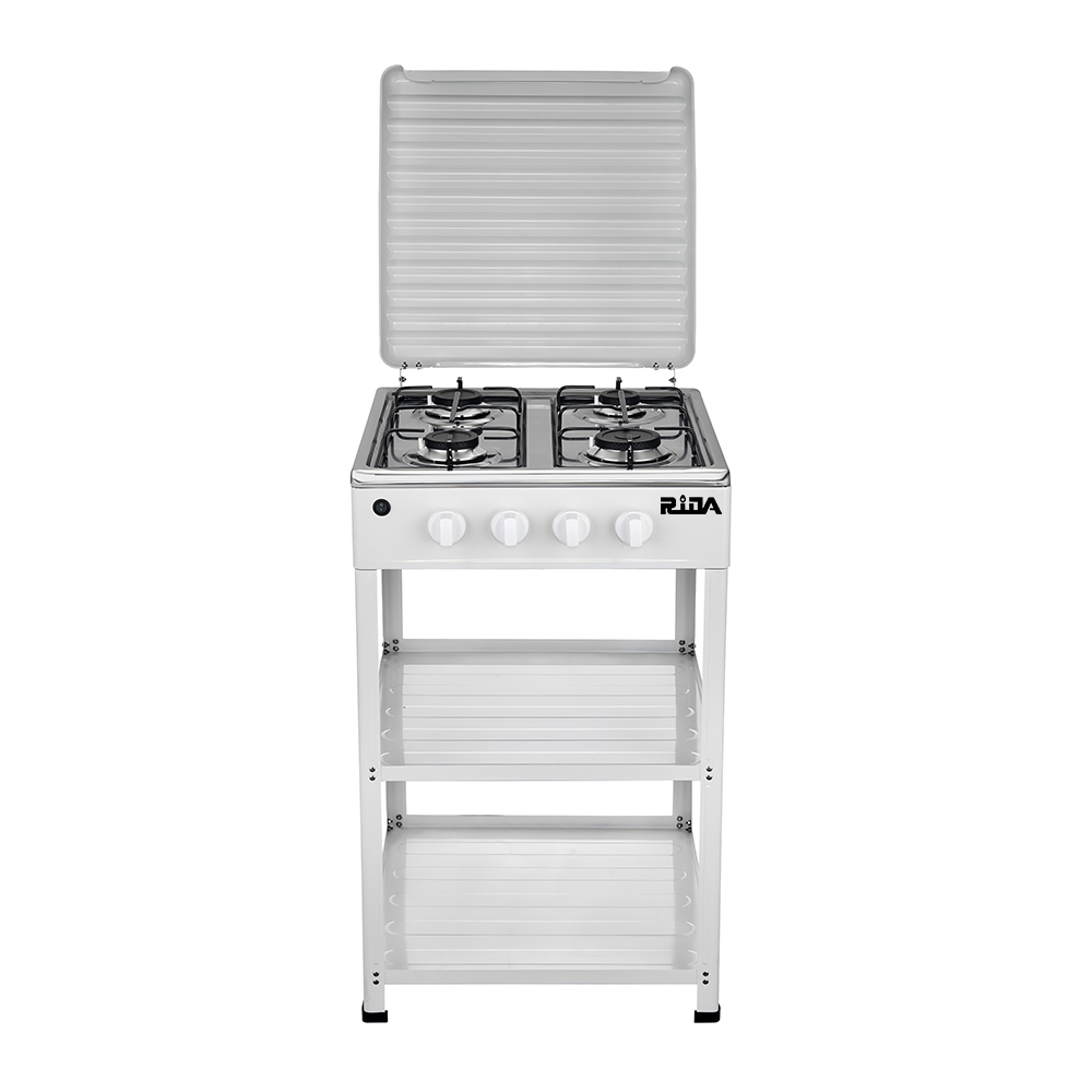
Choosing the right flexible gas connector dictates the safety of the entire setup. Sizing parameters include length and internal diameter. The hose must be long enough—typically 36 to 48 inches—to allow pulling the stand out for cleaning without stressing the connections. The internal diameter must match the total BTU output of the stove to prevent fuel starvation.
Adhere to strict industry standards: never reuse an old flexible gas connector. Metal fatigue and compromised seals make older hoses highly susceptible to leaks when repositioned. Always purchase a new, certified connector for every installation.
Gas Connector Sizing based on Appliance BTU | ||
Internal Diameter (ID) | Maximum BTU Capacity | Typical Application |
|---|---|---|
1/4 inch | Up to 48,000 BTU | Small space heaters, low-output cooktops. |
3/8 inch | Up to 106,000 BTU | Standard residential gas stoves. |
1/2 inch | Up to 164,000 BTU | High-output residential or light commercial stoves. |
3/4 inch | Up to 290,000 BTU | Heavy-duty commercial ranges. |
Proper sealing requires gas-rated pipe joint compound or yellow gas-line Teflon tape. Never use standard white plumbing tape, as it degrades rapidly under gas pressure. Assemble the necessary tools, including dual adjustable wrenches or pipe wrenches. Using two wrenches prevents twisting the manifold and damaging the internal brass components.
Prepare a non-corrosive liquid leak detection solution. You can use a commercial leak detector fluid or mix a specific water and dish soap ratio. This solution is critical for verifying the integrity of every threaded joint once the gas is turned back on.
Two adjustable wrenches (10-inch or 12-inch).
Yellow gas-rated Teflon tape or approved pipe dope.
Commercial liquid leak detector or a 50/50 dish soap and water mix.
A heavy-duty level (at least 24 inches long).
Work gloves and safety glasses.
Begin by safely shutting off the gas supply at the local gas cock behind the stove. If a local valve is absent, shut off the main gas supply to the house. Turn on a burner on the old appliance to bleed residual pressure from the line before attempting disconnection.
Carefully disconnect the legacy appliance using two wrenches. Cap the old line temporarily if the new installation will be delayed. Move the old unit out of the workspace to provide ample room for assembling the new stand.
Assemble the stand mechanically, ensuring all load-bearing bolts are torqued to the manufacturer's specification. A loose frame will compromise the stability of the cooking surface. Once assembled, position the stand near the installation site.
Leveling the stand using its adjustable feet is critical. An unlevel stand causes uneven cooking and physical instability. More importantly, structural shifting places severe stress on the rigid gas piping connected to the flexible hose, leading to potential joint failure.
Place the assembled stand in its approximate final location.
Place a 24-inch level across the front edge of the stand.
Adjust the front leveling legs until the bubble is perfectly centered.
Move the level to the side edges and adjust the rear legs accordingly.
Verify levelness diagonally across the stand to ensure all four feet bear equal weight.
Wrap the male pipe threads with yellow Teflon tape or apply pipe dope. Avoid coating the first two threads to prevent internal system contamination. Attach the connector fittings to the gas supply valve and the stove’s pressure regulator.
Always use two wrenches during this process—one to hold the fitting stationary and one to tighten the nut. This technique prevents twisting the internal pipes or damaging the soft brass connectors. Tighten the fittings securely, but avoid over-torquing, which can crack the metal.
Once the connections are tight, slowly open the gas shut-off valve. Do not rely on your sense of smell to detect leaks. Apply the leak detection solution generously to all newly formed joints.
Watch closely for active bubbling, which indicates a failed test and an active leak. If you see bubbles, immediately shut off the gas, bleed the line, and re-thread the connection. Repeat the test until zero bubbles appear.
Pushing the unit back into its final position carries the risk of crushing or kinking the flexible gas line. Carefully guide the hose to coil naturally in the open space behind the unit. A kinked line restricts gas flow and creates a weak point susceptible to rupture.
Install anti-tip brackets, even for heavy stand-mounted units. These brackets prevent the appliance from tipping under forward load, such as a heavy pot placed on an open oven door. Tipping can sever the gas line instantly, causing a catastrophic leak.
Review the required integration with overhead ventilation systems. The exhaust hood must meet the CFM requirements based on the stove's total BTU output to remove combustion byproducts effectively. Ensure the electrical outlet is properly grounded if the unit features electronic ignition or integrated oven components.
Mandate the installation and testing of carbon monoxide detectors in the immediate vicinity of the kitchen prior to the stove's first use. Proper ventilation and monitoring are your primary defenses against carbon monoxide accumulation.
Ventilation CFM Requirements by Stove Output | |
Total Stove Output (BTU) | Minimum Recommended CFM |
|---|---|
Up to 40,000 BTU | 400 CFM |
40,000 - 60,000 BTU | 600 CFM |
60,000 - 90,000 BTU | 900 CFM |
Over 90,000 BTU | 1200+ CFM |
DIY installation is only viable if the existing shut-off valve is modern, accessible, and requires no hard-pipe modifications. If you are comfortable using wrenches and performing leak tests, a simple swap is manageable. However, many scenarios require a professional.
Hire a certified gas fitter if you need to relocate the gas line, convert from electric to gas, or upgrade the pipe diameter for high-BTU commercial-style stands. Furthermore, many jurisdictions legally require licensed professionals for any gas work.
Improper DIY installation can void the manufacturer's warranty. If a component fails due to incorrect fitting or improper gas pressure, the manufacturer will likely deny the claim. Always read the warranty terms before starting the project.
Consider the homeowner's insurance risks associated with unpermitted gas work. In the event of a fire or leak caused by faulty installation, your insurance provider may deny coverage if the work was not performed by a licensed professional or lacked necessary permits.
Run the surface burners for two minutes to bleed trapped air from the new gas lines.
Verify the burner flame color is a solid, stable blue with no flickering yellow tipping.
Install and test a carbon monoxide detector within 15 feet of the newly installed appliance.
Schedule an annual inspection of the gas connections and flexible hose to maintain long-term safety.
A: Yes, you need a flexible stainless steel connector rated for the exact BTU output of the stove, with enough length to safely move the stand for cleaning without stressing the line.
A: Apply a specialized liquid leak detector or a thick soap-and-water solution to all connection points while the gas valve is open. Any bubbling indicates a leak.
A: No. Only use yellow Teflon tape or pipe joint compound specifically rated for gas lines. Standard white tape degrades under gas pressure.
A: Clearances vary by manufacturer but typically require 0-3 inches at the back and sides below the cooktop, and 6-12 inches for adjacent combustible cabinetry above the cooktop.
A: Yes. Regardless of the stand's weight, anti-tip brackets are legally required safety devices to prevent the unit from tipping and severing the gas line if weight is applied to an open door or the front of the unit.
A: Never. Flexible gas connectors are designed for single-use installation. Reusing them significantly increases the risk of micro-fractures and gas leaks.
A: Lay down heavy-duty cardboard, hardboard sheets, or specialized appliance sliders under the feet of the stand before positioning the unit. Never drag the bare metal stand legs directly across tile, wood, or vinyl flooring.


